|
Type |
|
|
Size |
NPS 1/8”~4” DN 6~100 |
|
Rating Pressure |
Threaded End – 2000 / 3000 / 6000 LBS. Socket-weld End – 3000 / 6000 / 9000 LBS. Butt-weld End – SCH40 / SCH80 / SCH160 / XXS. |
|
Specifications |
ASME B16.11-2009 (Revision of ASME B16.11-2005) MSS – SP – 79, 83, 95, 97 and BS3799.
ASTM A105, A350 LF2, A106, A312, A234, A403
|
|
Marking |
|
|
Finishing |
Carbon steel: Galvanized or black. Stainless steel: Pickled. |
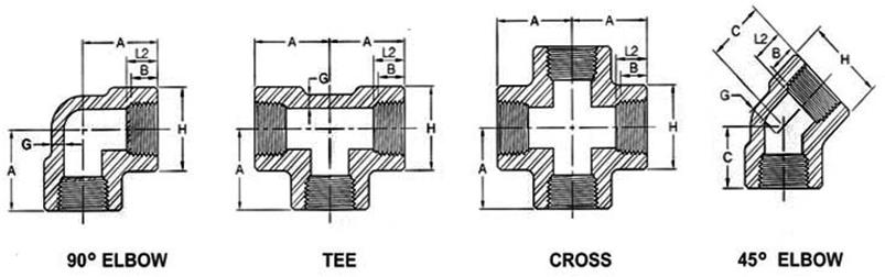
ASME B16.11-2009 (Revision of ASME B16.11-2005)
|
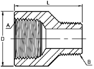
DN |
Nom. Pipe Size |
Center to End Elbow, Tee, Cross A |
Center to End 45° Elbow |
Outside Diameter Of Band |
Minimum Wall Thickness |
Length of Thread Min. (1) |
|||||||||
|
2000 |
3000 |
6000 |
2000 |
3000 |
6000 |
2000 |
3000 |
6000 |
2000 |
3000 |
6000 |
B |
L2 |
||
|
6 |
1/8” |
21 |
21 |
25 |
17 |
17 |
19 |
22 |
22 |
25 |
3.18 |
3.18 |
6.35 |
6.4 |
6.7 |
|
8 |
1/4” |
21 |
25 |
28 |
17 |
19 |
22 |
22 |
25 |
33 |
3.18 |
3.30 |
6.60 |
8.1 |
10.2 |
|
10 |
3/8” |
25 |
28 |
33 |
19 |
22 |
25 |
25 |
33 |
38 |
3.18 |
3.51 |
6.98 |
9.1 |
10.4 |
|
15 |
1/2” |
28 |
33 |
38 |
22 |
25 |
28 |
33 |
38 |
46 |
3.18 |
4.09 |
8.15 |
10.9 |
13.6 |
|
20 |
3/4” |
33 |
38 |
44 |
25 |
28 |
33 |
38 |
46 |
56 |
3.18 |
4.32 |
8.53 |
12.7 |
13.9 |
|
25 |
1” |
38 |
44 |
51 |
28 |
33 |
35 |
46 |
56 |
62 |
3.68 |
4.98 |
9.93 |
14.7 |
17.3 |
|
32 |
1-1/4” |
44 |
51 |
60 |
33 |
35 |
43 |
56 |
62 |
75 |
3.89 |
5.28 |
10.59 |
17.0 |
18.0 |
|
40 |
1-1/2” |
51 |
60 |
64 |
35 |
43 |
44 |
62 |
75 |
84 |
4.01 |
5.56 |
11.07 |
17.8 |
18.4 |
|
50 |
2” |
60 |
64 |
83 |
43 |
44 |
52 |
75 |
84 |
102 |
4.27 |
7.14 |
12.09 |
19.0 |
19.2 |
|
65 |
2-1/2” |
76 |
83 |
95 |
52 |
52 |
64 |
92 |
102 |
121 |
5.61 |
7.65 |
15.29 |
23.6 |
28.9 |
|
80 |
3” |
86 |
95 |
106 |
64 |
64 |
79 |
109 |
121 |
146 |
5.99 |
8.84 |
16.64 |
25.9 |
30.5 |
|
100 |
4” |
106 |
114 |
114 |
79 |
79 |
79 |
146 |
152 |
152 |
6.55 |
11.18 |
18.67 |
27.7 |
33.0 |
ASME B16.11-2009 (Revision of ASME B16.11-2005)
|
DN |
Nom. Pipe |
Center to End Coupling W |
Center to End Cap P |
Outside Diameter D |
End Wall Thickness G Min. |
Length of Thread Min. (1) |
||||
|
|
3000 & 6000 |
3000 |
6000 |
3000 |
6000 |
3000 |
6000 |
B |
L2 |
|
|
6 |
1/8” |
32 |
19 |
|
16 |
|
4.8 |
|
6.4 |
6.7 |
|
8 |
1/4” |
35 |
25 |
27 |
19 |
25 |
4.8 |
6.4 |
8.1 |
10.2 |
|
10 |
3/8” |
38 |
25 |
27 |
22 |
32 |
4.8 |
6.4 |
9.1 |
10.4 |
|
15 |
1/2” |
48 |
32 |
33 |
28 |
38 |
6.4 |
7.9 |
10.9 |
13.6 |
|
20 |
3/4” |
51 |
37 |
38 |
35 |
44 |
6.4 |
7.9 |
12.7 |
13.9 |
|
25 |
1” |
60 |
41 |
43 |
44 |
57 |
9.7 |
11.2 |
14.7 |
17.3 |
|
32 |
1-1/4” |
67 |
44 |
46 |
57 |
64 |
9.7 |
11.2 |
17.0 |
18.0 |
|
40 |
1-1/2” |
79 |
44 |
48 |
64 |
76 |
11.2 |
12.7 |
17.8 |
18.4 |
|
50 |
2” |
86 |
48 |
51 |
76 |
92 |
12.7 |
15.7 |
19.0 |
19.2 |
|
65 |
2-1/2” |
92 |
60 |
64 |
92 |
108 |
15.7 |
19.0 |
23.6 |
28.9 |
|
80 |
3” |
108 |
65 |
68 |
108 |
127 |
19.0 |
22.4 |
25.9 |
30.5 |
|
100 |
4” |
121 |
68 |
75 |
140 |
159 |
22.4 |
28.4 |
27.7 |
33.0 |
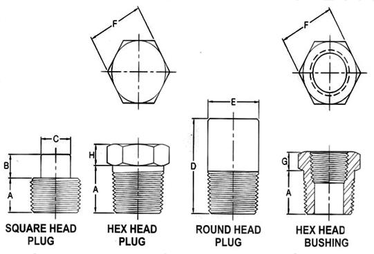
ASME B16.11-2009 (Revision of ASME B16.11-2005)
|
DN |
Nom. Pipe Size |
Length (Min.)
A |
Square Head Plug |
Round Head Plug |
Hex. Head Plug & Bushing |
||||
|
Height of Square (Min.) B |
Width Flat (Min.)
C |
Nominal Diameter of Head (Nom) |
Length (Min.)
D |
Width Flat (Nom.)
F |
Hex. Height (Min.) |
||||
|
Bushing G |
Plug H |
||||||||
|
6 |
1/8” |
10 |
6 |
7 |
10 |
35 |
|
|
6 |
|
8 |
1/4” |
11 |
6 |
10 |
14 |
41 |
16 |
3 |
6 |
|
10 |
3/8” |
13 |
8 |
11 |
18 |
41 |
18 |
4 |
8 |
|
15 |
1/2” |
14 |
10 |
14 |
21 |
44 |
22 |
5 |
8 |
|
20 |
3/4” |
16 |
11 |
16 |
27 |
44 |
27 |
6 |
10 |
|
25 |
1” |
19 |
13 |
21 |
33 |
51 |
36 |
6 |
10 |
|
32 |
1-1/4” |
21 |
14 |
24 |
43 |
51 |
46 |
7 |
14 |
|
40 |
1-1/2” |
21 |
16 |
28 |
48 |
51 |
50 |
8 |
16 |
|
50 |
2” |
22 |
18 |
32 |
60 |
64 |
65 |
9 |
18 |
|
65 |
2-1/2” |
27 |
19 |
36 |
73 |
70 |
75 |
10 |
19 |
|
80 |
3” |
28 |
21 |
41 |
89 |
70 |
90 |
10 |
21 |
|
100 |
4” |
32 |
25 |
65 |
114 |
76 |
115 |
13 |
25 |
Hex head bushing of one-size reduction should not be used in services where they might be subject to harmful loads and forces other than internal pressure.
Threaded End MSS-SP-83-2006
|
Nom. Pipe Size |
Pipe End |
Wall |
Water Way Bore |
Male Flange |
Nut |
Threads Per 25.4mm |
Bearing |
Length Assem. Nom. |
Clear Assem. Nut |
|
Min. A |
Min. C |
D |
Min. F |
Min. G |
Max. H |
Min. J |
L |
N |
|
|
1/8” |
14.7 |
2.41 |
8.43 |
3.18 |
3.18 |
16 |
1.24 |
41.4 |
50.8 |
|
1/4” |
19.0 |
3.02 |
11.13 |
3.18 |
3.18 |
16 |
1.24 |
41.4 |
50.8 |
|
3/8” |
22.9 |
3.20 |
14.27 |
3.43 |
3.43 |
14 |
1.37 |
46.0 |
55.9 |
|
1/2” |
27.7 |
3.73 |
17.86 |
3.68 |
3.68 |
14 |
1.50 |
49.0 |
58.4 |
|
3/4” |
33.5 |
3.91 |
23.01 |
4.06 |
4.06 |
11 |
1.68 |
56.9 |
66.0 |
|
1” |
41.4 |
4.55 |
28.98 |
4.57 |
4.45 |
11 |
1.85 |
62.0 |
78.7 |
|
1-1/4” |
50.5 |
4.85 |
37.69 |
5.33 |
5.21 |
11 |
2.13 |
71.1 |
94.0 |
|
1-1/2” |
57.2 |
5.08 |
43.54 |
5.84 |
5.59 |
10 |
2.31 |
76.5 |
111.8 |
|
2” |
70.1 |
5.54 |
55.58 |
6.60 |
6.35 |
10 |
2.69 |
86.1 |
132.1 |
|
2-1/2” |
85.3 |
7.01 |
66.27 |
7.49 |
7.11 |
8 |
3.07 |
102.4 |
149.9 |
|
3” |
102.4 |
7.62 |
88.25 |
8.26 |
8.00 |
8 |
3.53 |
109.0 |
175.3 |
|
Nominal Size |
A (Min) |
W (Min) |
E (Min) |
b |
C (Min) |
F (Min) |
||
|
DN |
Inch |
3000 |
6000 |
|||||
|
6 |
1/8” |
11 |
26 |
10 |
5 |
2 |
6 |
- |
|
8 |
1/4” |
15 |
36 |
15 |
8 |
6 |
6 |
- |
|
8 x 6 |
1/4”x1/8” |
15 |
31 |
15 |
5 |
2 |
6 |
10 |
|
10 |
3/8” |
18 |
40 |
16 |
11 |
8 |
8 |
- |
|
10 x 8 |
3/8”x1/4” |
18 |
39 |
16 |
8 |
6 |
8 |
15 |
|
15 |
1/2” |
22 |
48 |
20 |
14 |
11 |
8 |
- |
|
15 x 10 |
1/2”x3/8” |
22 |
44 |
20 |
11 |
8 |
8 |
16 |
|
15 x 8 |
1/2”x1/4” |
22 |
43 |
20 |
8 |
6 |
8 |
15 |
|
20 |
3/4” |
27 |
52 |
21 |
19 |
13 |
10 |
- |
|
20 x 15 |
3/4”x1/2” |
27 |
50 |
21 |
14 |
11 |
9 |
20 |
|
20 x 10 |
3/4”x3/8” |
27 |
46 |
21 |
11 |
8 |
9 |
16 |
|
25 |
1” |
35 |
60 |
25 |
24 |
17 |
10 |
- |
|
25 x 20 |
1”x3/4” |
35 |
56 |
25 |
19 |
13 |
10 |
21 |
|
25 x 15 |
1”x1/2” |
35 |
55 |
25 |
14 |
11 |
10 |
20 |
|
40 |
1-1/2” |
50 |
68 |
26 |
38 |
30 |
16 |
- |
|
40 x 25 |
1-1/2”x1” |
50 |
67 |
26 |
24 |
17 |
16 |
25 |
|
40 x 20 |
1-1/2”x3/4” |
50 |
63 |
26 |
19 |
13 |
16 |
21 |
|
40 x 15 |
1-1/2”x1/2” |
50 |
62 |
26 |
14 |
11 |
16 |
20 |
|
50 |
2” |
62 |
71 |
27 |
49 |
39 |
17 |
- |
|
50 x 40 |
2”x1-1/2” |
62 |
70 |
27 |
38 |
30 |
17 |
26 |
|
50 x 25 |
2”x1” |
62 |
70 |
27 |
24 |
17 |
18 |
25 |
|
50 x 20 |
2”x3/4” |
62 |
65 |
27 |
19 |
13 |
17 |
21 |
|
50 x 15 |
2”x1/2” |
62 |
65 |
27 |
14 |
11 |
18 |
20 |
Street Elbows Threaded
Threaded End ASME B16.11-2009 (Revision of ASME B16.11-2005)
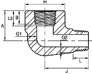
|
DN |
Nom. Pipe Size |
H |
A |
J |
G1 |
G2 (1) |
B (2) |
L2 (2) |
L (Min) |
|||||
|
3000 |
6000 |
3000 |
6000 |
3000 |
6000 |
3000 |
6000 |
3000 |
6000 |
|||||
|
6 |
1/8” |
19 |
25 |
19 |
22 |
25 |
32 |
3.18 |
5.08 |
2.74 |
4.22 |
6.4 |
6.7 |
10.0 |
|
8 |
1/4” |
25 |
32 |
22 |
25 |
32 |
38 |
3.30 |
5.66 |
3.22 |
5.28 |
8.1 |
10.2 |
11.0 |
|
10 |
3/8” |
32 |
38 |
25 |
28 |
38 |
41 |
3.50 |
6.98 |
3.50 |
5.59 |
9.1 |
10.4 |
13.0 |
|
15 |
1/2 |
38 |
44 |
28 |
35 |
41 |
48 |
4.09 |
8.15 |
4.16 |
6.53 |
10.9 |
13.6 |
14.0 |
|
20 |
3/4 |
44 |
51 |
35 |
44 |
48 |
57 |
4.32 |
8.53 |
4.88 |
6.86 |
12.7 |
13.9 |
16.0 |
|
25 |
1 |
51 |
62 |
44 |
51 |
57 |
66 |
4.98 |
9.93 |
5.56 |
7.95 |
14.7 |
17.3 |
19.0 |
|
32 |
1-1/4 |
62 |
70 |
51 |
54 |
66 |
71 |
5.28 |
10.59 |
5.56 |
8.48 |
17.0 |
18.0 |
21.0 |
|
40 |
1-1/2 |
70 |
84 |
54 |
64 |
71 |
84 |
5.56 |
11.07 |
6.25 |
8.89 |
17.8 |
18.4 |
21.0 |
|
50 |
2 |
84 |
102 |
64 |
83 |
84 |
105 |
7.14 |
12.09 |
7.64 |
9.70 |
19.0 |
19.0 |
22.0 |
MSS-SP-95-2006

|
Nom. Pipe Size |
|
|
|
T (Min) |
|
|||
|
D |
B |
B1 |
Sch.40 (STD) |
Sch.80 (XS) |
Sch.160 |
XXS |
H |
|
|
1/8” |
10.3 |
34 |
9.5 |
1.73 |
2.41 |
|
|
14 |
|
1/4” |
13.7 |
34 |
11.0 |
2.24 |
3.02 |
|
|
14 |
|
3/8” |
17.1 |
57 |
12.5 |
2.31 |
3.20 |
|
|
14 |
|
1/2” |
21.3 |
64 |
14.5 |
2.77 |
3.73 |
4.78 |
7.47 |
14 |
|
3/4” |
26.7 |
70 |
16.0 |
2.87 |
3.91 |
5.56 |
7.82 |
18 |
|
1” |
33.4 |
76 |
19.0 |
3.38 |
4.56 |
6.35 |
9.09 |
18 |
|
1-1/4” |
42.2 |
83 |
20.5 |
3.56 |
4.85 |
6.35 |
9.70 |
18 |
|
1-1/2” |
48.3 |
89 |
20.5 |
3.68 |
5.05 |
7.14 |
10.15 |
18 |
|
2” |
60.3 |
102 |
22.0 |
3.91 |
5.54 |
8.74 |
11.07 |
20 |
|
2-1/2” |
73.0 |
127 |
27.0 |
5.16 |
7.01 |
9.53 |
14.02 |
20 |
|
3” |
88.9 |
152 |
28.5 |
5.49 |
7.60 |
11.13 |
15.24 |
20 |
|
4” |
114.3 |
178 |
32.0 |
6.35 |
8.08 |
13.49 |
17.12 |
20 |
 Dimensions
in Millimeters.
Dimensions
in Millimeters.
BS3799-1974
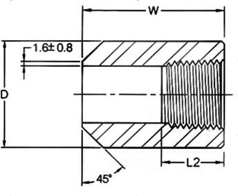
|
DN |
Nom. Pipe Size |
D |
W |
L2 |
|||
|
3000lb |
6000lb |
3000lb |
6000lb |
3000lb |
6000lb |
||
|
6 |
1/8” |
16.0 |
22.0 |
38.0 |
6.70 |
||
|
8 |
1/4” |
19.0 |
26.0 |
41.0 |
10.21 |
||
|
10 |
3/8” |
22.0 |
32.0 |
45.0 |
10.36 |
||
|
15 |
1/2” |
29.0 |
38.0 |
51.0 |
13.56 |
||
|
20 |
3/4” |
35.0 |
45.0 |
51.0 |
13.86 |
||
|
25 |
1” |
45.0 |
60.0 |
51.0 |
17.34 |
||
|
40 |
1-1/2” |
64.0 |
76.0 |
51.0 |
18.38 |
||
|
50 |
2” |
76.0 |
95.0 |
51.0 |
19.22 |
||
|
65 |
2-1/2” |
95.0 |
|
51.0 |
|
28.89 |
|
|
80 |
3” |
110.0 |
|
57.0 |
|
30.48 |
|
|
100 |
4” |
140.0 |
|
64.0 |
|
33.02 |
|


 Dimensions in Millimeters.
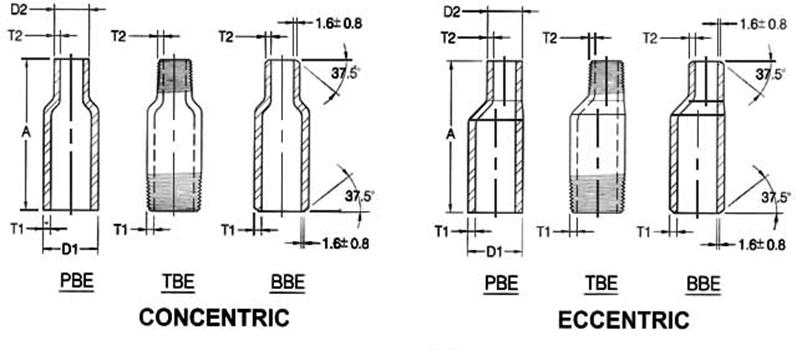

![]() (Continued)
(Continued)
Nominal Pipe Size (NPS) |
Outside Diameter |
End To End |
Wall Thickness |
||||||||
|
Large End D1 |
Small End D2 |
T1 |
T2 |
||||||||
|
Sch40 (STD) |
Sch80 (XS) |
Sch160 |
XXS |
Sch40 (STD) |
Sch80 (XS) |
Sch160 |
XXS |
||||
|
3-1/2”x1-1/2” |
101.6 |
48.3 |
203 |
5.7 |
8.1 |
|
|
3.7 |
5.1 |
7.1 |
10.2 |
|
3-1/2”x2” |
101.6 |
60.3 |
203 |
5.7 |
8.1 |
|
|
3.9 |
5.5 |
8.7 |
11.1 |
|
3-1/2”x2-1/2” |
101.6 |
73.0 |
203 |
5.7 |
8.1 |
|
|
5.2 |
7.0 |
9.5 |
14.0 |
|
3-1/2”x3” |
101.6 |
88.9 |
203 |
5.7 |
8.1 |
|
|
5.5 |
7.6 |
11.1 |
15.2 |
|
4”x1/4” |
114.3 |
13.7 |
229 |
6.0 |
8.6 |
13.5 |
17.1 |
2.2 |
3.0 |
|
|
|
4”x3/8” |
114.3 |
17.1 |
229 |
6.0 |
8.6 |
13.5 |
17.1 |
2.3 |
3.2 |
|
|
|
4”x1/2” |
114.3 |
21.3 |
229 |
6.0 |
8.6 |
13.5 |
17.1 |
2.8 |
3.7 |
4.8 |
7.5 |
|
4”x3/4” |
114.3 |
26.7 |
229 |
6.0 |
8.6 |
13.5 |
17.1 |
2.9 |
3.9 |
5.6 |
7.8 |
|
4”x1” |
114.3 |
33.4 |
229 |
6.0 |
8.6 |
13.5 |
17.1 |
3.4 |
4.5 |
6.4 |
9.1 |
|
4”x1-1/4” |
114.3 |
42.2 |
229 |
6.0 |
8.6 |
13.5 |
17.1 |
3.6 |
4.9 |
6.4 |
9.7 |
|
4”x1-1/2” |
114.3 |
48.3 |
229 |
6.0 |
8.6 |
13.5 |
17.1 |
3.7 |
5.1 |
7.1 |
10.2 |
|
4”x2” |
114.3 |
60.3 |
229 |
6.0 |
8.6 |
13.5 |
17.1 |
3.9 |
5.5 |
8.7 |
11.1 |
|
4”x2-1/2” |
114.3 |
73.0 |
229 |
6.0 |
8.6 |
13.5 |
17.1 |
5.2 |
7.0 |
9.5 |
14.0 |
|
4”x3” |
114.3 |
88.9 |
229 |
6.0 |
8.6 |
13.5 |
17.1 |
5.5 |
7.6 |
11.1 |
15.2 |
|
4”x3-1/2” |
114.3 |
101.6 |
229 |
6.0 |
8.6 |
13.5 |
17.1 |
5.7 |
8.1 |
|
|
|
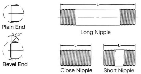
PBE:Plain Both Ends |
BBE:Bevel Both Ends |
TBE:Thread Both Ends |
|
PSE:Plain Small End |
BSE:Bevel Small End |
TSE:Thread Small End |
|
PLE:Plain Large End |
BLE:Bevel Large End |
TLE:Thread Large End |
|
Nominal Pipe Size (inch) |
Overall Length (mm) |
Outside diameter at end |
Wall Thickness (prior to threading or grooving) |
|
|
Square Cut Ends (mm) |
Other End Connection (mm) |
|||
|
1/8” to 3/8” |
± 1.5 |
+ 0.40 |
± 0.80 |
Not less than 87.5% of nominal wall thickness |
|
- 0.80 |
||||
|
1/2” to 1-1/2” |
± 1.5 |
+ 0.40 |
+ 1.50 |
|
|
- 0.80 |
- 0.80 |
|||
|
2” to 2-1/2” |
± 3.0 |
± 0.80 |
+ 1.50 |
|
|
- 0.80 |
||||
|
3” to 4” |
± 3.0 |
± 0.80 |
± 1.50 |
|

|
Nom. Pipe Size |
L |
Plain End Weight (kg/m) |
|||||
|
Close Nipple |
Short Nipple |
Long Nipple |
Sch40/STD |
Sch80/XS |
Sch160 |
XXS |
|
|
1/8” |
3/4 |
1-1/2 |
2~12 |
0.37 |
0.47 |
|
|
|
1/4” |
7/8 |
1-1/2 |
2~12 |
0.63 |
0.80 |
|
|
|
3/8” |
1 |
1-1/2 |
2~12 |
0.84 |
1.10 |
|
|
|
1/2” |
1-1/8 |
1-1/2 |
2~12 |
1.27 |
1.62 |
1.95 |
2.55 |
|
3/4” |
1-3/8 |
2 |
2-1/2~12 |
1.69 |
2.20 |
2.90 |
3.64 |
|
1” |
1-1/2 |
2 |
2-1/2~12 |
2.50 |
3.24 |
4.24 |
5.45 |
|
1-1/4” |
1-5/8 |
2-1/2 |
3~12 |
3.39 |
4.47 |
5.61 |
7.77 |
|
1-1/2” |
1-3/4 |
2-1/2 |
3~12 |
4.05 |
5.41 |
7.25 |
9.55 |
|
2” |
2 |
2-1/2 |
3~12 |
5.44 |
7.48 |
11.11 |
13.44 |
|
2-1/2” |
2-1/2 |
3 |
3-1/2~12 |
8.63 |
11.41 |
14.92 |
20.39 |
|
3” |
2-5/8 |
3 |
3-1/2~12 |
11.29 |
15.27 |
21.35 |
27.68 |
|
3-1/2” |
2-3/4 |
4 |
4-1/2~12 |
13.57 |
18.64 |
|
|
|
4” |
2-7/8 |
4 |
4-1/2~12 |
16.08 |
22.32 |
33.54 |
41.03 |
|
5” |
3 |
4-1/2 |
5~12 |
21.77 |
30.97 |
49.12 |
57.43 |
|
6” |
3-1/8 |
4-1/2 |
5~12 |
28.26 |
42.56 |
67.57 |
79.22 |


 Shape of Thread
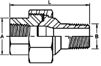
Adapter Threaded
3000LB
|
DN |
Nom Pipe Size A |
D |
L |
Threaded Size B |
|
8 |
1/4” |
19 |
33 |
1/8” |
|
10 |
3/8” |
22 |
35 |
1/4” |
|
15 |
1/2” |
28 |
42 |
3/8” |
|
20 |
3/4” |
35 |
47 |
1/2” |
|
25 |
1” |
44 |
55 |
3/4” |
|
32 |
1-1/4” |
57 |
63 |
1” |
|
40 |
1-1/2” |
64 |
66 |
1-1/4” |
|
50 |
2” |
76 |
76 |
1-1/2” |
|
65 |
2-1/2” |
92 |
90 |
2” |
|
80 |
3” |
108 |
110 |
2-1/2” |
|
100 |
4” |
140 |
120 |
3” |
|
Nom Pipe Size |
A (2) |
B |
L |
|
1/4” |
19.0 |
13.7 |
55.4 |
|
3/8” |
22.9 |
17.1 |
60.0 |
|
1/2” |
27.7 |
21.3 |
68.0 |
|
3/4” |
33.5 |
26.7 |
75.9 |
|
1” |
41.4 |
33.4 |
86.0 |
|
1-1/4” |
50.5 |
42.2 |
95.1 |
|
1-1/2” |
57.2 |
48.3 |
100.5 |
|
2” |
70.1 |
60.3 |
112.1 |
Dimensions may vary according to the customers’ and manufacturer’s requirement


![]()


 Thread in
accordance with ASME B1.20.1
Thread in
accordance with ASME B1.20.1|
Item |
1/8” to 3/4” |
1” to 4” |
|
Face of fitting to crotch (A) |
± 0.76 |
± 1.52 |
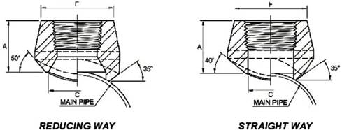
Conventional Run Size Combinations
|
|
OUTLET SIZE |
|||||||||||
|
1/4” |
3/8” |
1/2” |
3/4” |
1” |
1-1/4” |
1-1/2” |
2” |
2-1/2” |
3” |
4” |
||
|
RUN SIZE (Main Pipe) |
Reducing way |
3/8”~3/4” |
1/2” |
3/4” |
1” |
1-1/4” |
1-1/2” |
2” |
2-1/2” |
3” |
3-1/2” |
5” |
|
1”~36” |
3/4”~1-1/4” |
1” |
1-1/4” |
1-1/2” |
2” |
2-1/2” |
3” |
3-1/2” |
4” |
6” |
||
|
|
1-1/2”~36” |
1-1/4” |
1-1/2” |
2” |
2-1/2” |
3” |
3-1/2” |
4” |
5” |
8” |
||
|
|
|
1-1/2”~3” |
2”~3” |
2-1/2” |
3” |
3-1/2” |
4” |
5” |
6” |
10” |
||
|
|
|
3-1/2”~36” |
3-1/2”~6” |
3” |
3-1/2”~5” |
4”~5” |
5”~6” |
6” |
8” |
12”~14” |
||
|
|
|
|
8”~36” |
3-1/2”~4” |
6”~8” |
6”~10” |
8”~10” |
8” |
10” |
16”~18” |
||
|
|
|
|
|
5”~10” |
10” ~ 36” |
12”~36” |
12”~18” |
10”~14” |
12”~16” |
20”~24” |
||
|
|
|
|
|
12~36” |
|
|
20”~36” |
16”~36” |
18”~36” |
26”~36” |
||
|
Straight way |
|
|
|
|
|
|
|
|
|
3-1/2” |
5” |
|
|
3/8”~36” |
1/2”~36” |
3/4”~36” |
1”~36” |
1-1/4”~1-1/2” |
1-1/2” |
2” |
2-1/2” |
3” |
4” |
6” |
||
|
|
|
|
|
|
|
|
|
|
14”~36” |
18”~36” |
||
Each charted outlet size is designed to fit a number of run pipe size.
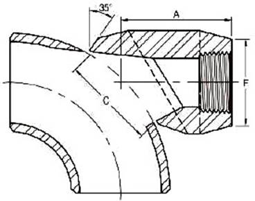
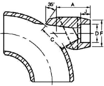
|
Outlet Pipe |
A |
C |
F |
|
|
DN |
Inch |
|||
|
8 |
1/4” |
40.5 |
35.2 |
22.0 |
|
10 |
3/8” |
40.5 |
35.2 |
25.9 |
|
15 |
1/2” |
40.5 |
35.2 |
31.4 |
|
20 |
3/4” |
47.6 |
43.6 |
37.1 |
|
25 |
1” |
55.6 |
54.0 |
45.5 |
|
32 |
1-1/4” |
60.3 |
67.5 |
57.0 |
|
40 |
1-1/2” |
66.7 |
76.2 |
64.0 |
|
50 |
2” |
81.0 |
104.8 |
76.0 |
|
65 |
2-1/2” |
82.6 |
106.4 |
92.0 |
|
80 |
3” |
96.8 |
125.4 |
109.2 |
|
100 |
4” |
114.3 |
163.5 |
140.0 |
6000LB
Outlet Pipe |
A |
C |
F |
|
|
DN |
Inch |
|||
|
8 |
1/4” |
40.5 |
34.9 |
26.0 |
|
10 |
3/8” |
40.5 |
34.9 |
33.0 |
|
15 |
1/2” |
47.6 |
34.9 |
38.0 |
|
20 |
3/4” |
55.6 |
43.6 |
44.0 |
|
25 |
1” |
60.3 |
54.0 |
57.0 |
|
32 |
1-1/4” |
66.7 |
67.5 |
64.0 |
|
40 |
1-1/2” |
85.7 |
76.2 |
76.0 |
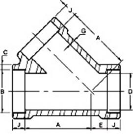
45° Lateral Tee Threaded
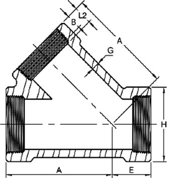
|
DN |
Nom. Pipe Size |
Length of Thread (Min) |
A |
E |
G (2) |
H (2) |
|
|
B (3) |
L2 (3) |
||||||
|
15 |
1/2” |
10.9 |
13.6 |
46 |
20 |
3.18 |
33 |
|
20 |
3/4” |
12.7 |
13.9 |
55 |
23 |
3.18 |
38 |
|
25 |
1” |
14.7 |
17.3 |
65 |
26 |
3.68 |
46 |
|
32 |
1-1/4” |
17.0 |
18.0 |
73 |
31 |
3.89 |
56 |
|
40 |
1-1/2” |
17.8 |
18.4 |
82 |
35 |
4.01 |
62 |
|
50 |
2” |
19.0 |
19.2 |
113 |
42 |
4.27 |
75 |
|
65 |
2-1/2” |
23.6 |
28.9 |
136 |
56 |
5.61 |
92 |
3000LB
DN |
Nom. Pipe Size |
Length of Thread (Min) |
A |
E |
G (2) |
H (2) |
|
|
B (3) |
L2 (3) |
||||||
|
15 |
1/2” |
10.9 |
13.6 |
55 |
23 |
4.09 |
38 |
|
20 |
3/4” |
12.7 |
13.9 |
65 |
26 |
4.32 |
46 |
|
25 |
1” |
14.7 |
17.3 |
73 |
31 |
4.98 |
56 |
|
32 |
1-1/4” |
17.0 |
18.0 |
82 |
35 |
5.28 |
62 |
|
40 |
1-1/2” |
17.8 |
18.4 |
113 |
42 |
5.56 |
75 |
|
50 |
2” |
19.0 |
19.2 |
136 |
56 |
7.14 |
84 |
The length of useful thread (B plus threads with fully formed roots and flat crests) shall not be less than L2 (effective length of external thread) required by American National Standard for pipe threads (ANSI/ASME B1.20.1)
Lateral Outlet Threaded
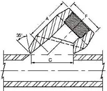
|
Outlet Pipe |
A |
C |
F |
|
|
DN |
Inch |
|||
|
8 |
1/4” |
40.5 |
35.2 |
22.0 |
|
10 |
3/8” |
40.5 |
35.2 |
25.9 |
|
15 |
1/2” |
40.5 |
35.2 |
31.4 |
|
20 |
3/4” |
47.6 |
43.6 |
37.1 |
|
25 |
1” |
55.6 |
54.0 |
45.5 |
|
32 |
1-1/4” |
60.3 |
67.5 |
57.0 |
|
40 |
1-1/2” |
66.7 |
76.2 |
64.0 |
|
50 |
2” |
81.0 |
104.8 |
76.0 |
|
65 |
2-1/2” |
82.6 |
106.4 |
92.0 |
|
80 |
3” |
96.8 |
125.4 |
109.2 |
|
100 |
4” |
114.3 |
163.5 |
140.0 |
6000LB
Outlet Pipe |
A |
C |
F |
|
|
DN |
Inch |
|||
|
8 |
1/4” |
40.5 |
34.9 |
26.0 |
|
10 |
3/8” |
40.5 |
34.9 |
33.0 |
|
15 |
1/2” |
47.6 |
34.9 |
38.0 |
|
20 |
3/4” |
55.6 |
43.6 |
44.0 |
|
25 |
1” |
60.3 |
54.0 |
57.0 |
|
32 |
1-1/4” |
66.7 |
67.5 |
64.0 |
|
40 |
1-1/2” |
85.7 |
76.2 |
76.0 |
|
Outlet Pipe |
C |
F |
|
|
3000LB |
6000LB |
||
|
1/2” |
23.8 |
13.8 |
21.3 |
|
3/4” |
30.2 |
18.9 |
26.7 |
|
1” |
36.5 |
24.3 |
33.4 |
|
1-1/4” |
44.5 |
32.5 |
42.2 |
|
1-1/2” |
50.8 |
38.1 |
48.3 |
|
2” |
65.1 |
49.2 |
60.3 |
Dimensions may vary according to the customer’s and manufacturer’s requirement
 Socket
Weld End MSS-SP-83-2006
Socket
Weld End MSS-SP-83-2006
|
Nom. Pipe Size |
Pipe End
(Min.) A |
Socket Bore Dia.
B |
Socket Wall
(Min.) C |
Water Way Bore D |
Laying Length
E |
Male Flange
(Min.) F |
Nut
(Min.) G |
Thread s Per 25.4mm
H |
Bearing
(Min.) J |
Depth of Socket (Min.) K |
Length Assem
L |
Clear Assem. Nut
N |
|
1/8” |
21.8 |
11.18 |
3.18 |
7.59 |
22.4 |
3.18 |
3.18 |
16 |
1.24 |
9.7 |
41.4 |
50.8 |
|
1/4” |
21.8 |
14.61 |
3.30 |
10.01 |
22.4 |
3.18 |
3.18 |
16 |
1.24 |
9.7 |
41.4 |
50.8 |
|
3/8” |
25.9 |
18.03 |
3.51 |
13.28 |
26.9 |
3.43 |
3.43 |
14 |
1.37 |
9.7 |
46.0 |
55.9 |
|
1/2” |
31.2 |
22.23 |
4.09 |
16.56 |
26.9 |
3.68 |
3.68 |
14 |
1.50 |
9.7 |
49.0 |
58.4 |
|
3/4” |
37.1 |
27.56 |
4.27 |
21.69 |
31.8 |
4.06 |
4.06 |
11 |
1.68 |
12.7 |
56.9 |
66.0 |
|
1” |
45.5 |
34.29 |
4.98 |
27.41 |
34.3 |
4.57 |
4.45 |
11 |
1.85 |
12.7 |
62.0 |
78.7 |
|
1-1/4” |
54.9 |
43.05 |
5.28 |
35.81 |
40.6 |
5.33 |
5.21 |
11 |
2.13 |
12.7 |
71.1 |
94.0 |
|
1-1/2” |
61.5 |
49.15 |
5.54 |
41.66 |
42.2 |
5.84 |
5.59 |
10 |
2.31 |
12.7 |
76.5 |
111.8 |
|
2” |
75.2 |
61.62 |
6.05 |
53.26 |
45.5 |
6.60 |
6.35 |
10 |
2.69 |
15.7 |
86.1 |
132.1 |
|
2-1/2” |
91.7 |
74.45 |
7.67 |
64.24 |
61.7 |
7.49 |
7.11 |
8 |
3.07 |
15.7 |
102.4 |
149.9 |
|
3” |
109.2 |
90.42 |
8.31 |
79.45 |
63.8 |
8.26 |
8.00 |
8 |
3.53 |
15.7 |
109.0 |
175.3 |
Upper and lower values for each size are the respective maximum and minimum dimensions
Socket Welding MSS-SP-79-2009
|
Nom. Pipe Size |
Type |
Socket |
Shank Dia. SD |
Laying Length A |
Bore D |
Wall Min. C |
Length |
||||||||
|
Dia. B |
Depth Min. K |
SL |
RL (Min) |
||||||||||||
|
3000 |
6000 |
||||||||||||||
|
3000 |
6000 |
3000 |
6000 |
3000 |
6000 |
3000 |
6000 |
3000 |
6000 |
||||||
|
3”x2-1/2” |
1 |
1 |
74.07 |
16 |
88.90 |
38 |
57 |
62.5 |
54.0 |
8.76 |
|
32 |
45 |
|
|
|
3”x2” |
2 |
2 |
61.37 |
16 |
88.90 |
25 |
32 |
52.5 |
43.0 |
6.93 |
|
|
|
48 |
54 |
|
3”x1-1/2” |
2 |
2 |
48.90 |
13 |
88.90 |
29 |
32 |
41.0 |
34.0 |
6.35 |
|
|
|
48 |
54 |
|
3”x1-1/4” |
2 |
2 |
42.80 |
13 |
88.90 |
30 |
32 |
35.0 |
29.5 |
6.07 |
|
|
|
48 |
54 |
|
3”x1” |
2 |
2 |
34.04 |
13 |
88.90 |
32 |
32 |
26.5 |
21.0 |
5.69 |
|
|
|
48 |
54 |
|
4”x3” |
2 |
|
90.04 |
16 |
114.30 |
33 |
|
78.0 |
|
9.50 |
|
|
|
60 |
|
|
4”x2-1/2” |
2 |
|
74.07 |
16 |
114.30 |
38 |
|
62.5 |
|
8.76 |
|
|
|
60 |
|
|
4”x2” |
2 |
|
61.37 |
16 |
114.30 |
38 |
|
52.5 |
|
6.93 |
|
|
|
60 |
|
|
4”x1-1/2” |
2 |
|
48.90 |
13 |
114.30 |
42 |
|
41.0 |
|
6.35 |
|
|
|
60 |
|
|
4”x1-1/4” |
2 |
|
42.80 |
13 |
114.30 |
43 |
|
35.0 |
|
6.07 |
|
|
|
60 |
|

 Dimensions
in Millimeters.
Dimensions
in Millimeters.Dimensional Tolerance of Reducer Insert
|
Laying Length A |
Size Size |
3/8” |
through through |
3/4” |
+ |
1.50mm / -0.00mm |
|
Socket Diameter B |
Size |
1/4” |
through |
2” |
± |
0.25mm |
|
Bore D |
Size |
1/4” |
through |
2” |
± |
0.80mm |
|
Shank Diameter SD |
Size |
3/8” |
through through |
1-1/2” |
± |
0.25mm |
|
Shank Length SL |
Size |
3/8” |
through |
3/4” |
± |
0.00mm / -1.50mm |
Bosses Socket Weld
BS3799-1974
|
DN |
Nom. Pipe Size |
B |
D |
J |
F |
C |
||||
|
3000lb |
6000lb |
3000lb |
6000lb |
3000lb |
6000lb |
3000lb |
6000lb |
|||
|
6 |
1/8” |
10.7 |
6.8 |
|
10.0 |
|
28.0 |
|
3.2 |
|
|
8 |
1/4” |
14.1 |
9.2 |
|
10.0 |
|
32.0 |
|
3.3 |
|
|
10 |
3/8” |
17.6 |
12.5 |
|
11.0 |
|
34.0 |
|
3.5 |
|
|
15 |
1/2” |
21.8 |
15.5 |
11.8 |
13.0 |
13.0 |
38.0 |
38.0 |
4.1 |
5.2 |
|
20 |
3/4” |
27.4 |
21.0 |
15.5 |
13.0 |
13.0 |
38.0 |
38.0 |
4.3 |
6.1 |
|
25 |
1” |
34.1 |
26.6 |
20.7 |
16.0 |
16.0 |
35.0 |
35.0 |
5.0 |
7.0 |
|
40 |
1-1/2” |
49.0 |
40.5 |
34.0 |
19.0 |
19.0 |
32.0 |
32.0 |
5.6 |
7.8 |
|
50 |
2” |
61.0 |
52.0 |
43.0 |
22.0 |
22.0 |
29.0 |
29.0 |
6.1 |
9.5 |
|
65 |
2-1/2” |
73.8 |
62.0 |
54.0 |
22.0 |
22.0 |
29.0 |
29.0 |
7.7 |
10.4 |
|
80 |
3” |
89.7 |
78.0 |
66.0 |
22.0 |
22.0 |
29.0 |
29.0 |
8.3 |
12.2 |


 Dimensions in
Millimeters.
Dimensions in
Millimeters.
|
Outlet Pipe |
A |
C |
F |
D |
J |
|
|
DN |
Inch |
|||||
|
8 |
1/4” |
40.5 |
35.2 |
22.0 |
14.35 |
10.0 |
|
10 |
3/8” |
40.5 |
35.2 |
25.9 |
17.80 |
10.0 |
|
15 |
1/2” |
40.5 |
35.2 |
31.4 |
21.95 |
11.1 |
|
20 |
3/4” |
47.6 |
43.6 |
37.1 |
27.30 |
12.7 |
|
25 |
1” |
55.6 |
54.0 |
45.5 |
34.05 |
13.5 |
|
32 |
1-1/4” |
60.3 |
67.5 |
57.0 |
42.80 |
15.1 |
|
40 |
1-1/2” |
66.7 |
76.2 |
64.0 |
48.90 |
15.9 |
|
50 |
2” |
81.0 |
104.8 |
76.0 |
61.35 |
17.5 |
|
65 |
2-1/2” |
82.6 |
106.4 |
92.0 |
74.15 |
23.8 |
|
80 |
3” |
96.8 |
125.4 |
109.2 |
90.10 |
28.6 |
|
100 |
4” |
114.3 |
163.5 |
140.0 |
115.75 |
29.4 |
6000LB
Outlet Pipe |
A |
C |
F |
D |
J |
|
|
DN |
Inch |
|||||
|
8 |
1/4” |
40.5 |
34.9 |
26.0 |
14.35 |
10.0 |
|
10 |
3/8” |
40.5 |
34.9 |
33.0 |
17.80 |
10.0 |
|
15 |
1/2” |
47.6 |
34.9 |
38.0 |
21.95 |
10.0 |
|
20 |
3/4” |
55.6 |
43.6 |
44.0 |
27.30 |
14.3 |
|
25 |
1” |
60.3 |
54.0 |
57.0 |
34.05 |
15.9 |
|
32 |
1-1/4” |
66.7 |
67.5 |
64.0 |
42.80 |
20.6 |
|
40 |
1-1/2” |
85.7 |
76.2 |
76.0 |
48.90 |
20.6 |
Dimensions may vary according to the customer’s and manufacturer’s requirement
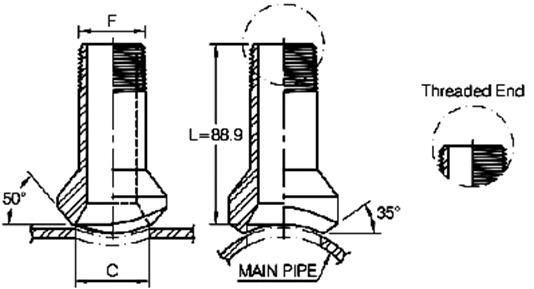
|
DN |
Nom. Pipe Size |
B (2) |
B (2) |
D (1) |
A |
E |
G (2) |
J (2) |
|
|
(Avg) |
(Min) |
||||||||
|
15 |
1/2” |
21.8 |
4.67 |
4.09 |
15.8 |
35 |
9 |
3.75 |
9.5 |
|
20 |
3/4” |
27.2 |
4.90 |
4.27 |
21.0 |
41 |
9 |
3.95 |
12.5 |
|
25 |
1” |
33.9 |
5.69 |
4.98 |
26.7 |
51 |
12 |
4.55 |
12.5 |
|
32 |
1-1/4” |
42.7 |
6.07 |
5.28 |
35.1 |
59 |
17 |
4.85 |
12.5 |
|
40 |
1-1/2” |
48.8 |
6.35 |
5.54 |
40.9 |
68 |
21 |
5.10 |
12.5 |
|
50 |
2” |
61.2 |
6.93 |
6.04 |
52.5 |
95 |
24 |
5.55 |
16.0 |
|
65 |
2-1/2” |
73.9 |
8.76 |
7.67 |
62.7 |
118 |
38 |
7.05 |
16.0 |
6000LB
|
DN |
Nom. Pipe Size |
B (2) |
B (2) |
D (2) |
A |
E |
G (2) |
J (2) |
|
|
(Avg) |
(Min) |
||||||||
|
15 |
1/2” |
21.8 |
5.97 |
5.18 |
11.8 |
41 |
9 |
4.78 |
9.5 |
|
20 |
3/4” |
27.2 |
6.96 |
6.04 |
15.6 |
51 |
12 |
5.56 |
12.5 |
|
25 |
1” |
33.9 |
7.92 |
6.93 |
20.7 |
59 |
17 |
6.35 |
12.5 |
|
32 |
1-1/4” |
42.7 |
7.92 |
6.93 |
29.5 |
68 |
21 |
6.35 |
12.5 |
|
40 |
1-1/2” |
48.8 |
8.92 |
7.80 |
34.0 |
95 |
24 |
7.14 |
12.5 |
|
50 |
2” |
61.2 |
10.92 |
9.50 |
42.9 |
106 |
31 |
8.74 |
16.0 |

|
Outlet Pipe |
A |
C |
F |
D |
J |
|
|
DN |
Inch |
|||||
|
8 |
1/4” |
40.5 |
35.2 |
22.0 |
14.35 |
10.0 |
|
10 |
3/8” |
40.5 |
35.2 |
25.9 |
17.80 |
10.0 |
|
15 |
1/2” |
40.5 |
35.2 |
31.4 |
21.95 |
11.1 |
|
20 |
3/4” |
47.6 |
43.6 |
37.1 |
27.30 |
12.7 |
|
25 |
1” |
55.6 |
54.0 |
45.5 |
34.05 |
13.5 |
|
32 |
1-1/4” |
60.3 |
67.5 |
57.0 |
42.80 |
15.1 |
|
40 |
1-1/2” |
66.7 |
76.2 |
64.0 |
48.90 |
15.9 |
|
50 |
2” |
81.0 |
104.8 |
76.0 |
61.35 |
17.5 |
|
65 |
2-1/2” |
82.6 |
106.4 |
92.0 |
74.15 |
23.8 |
|
80 |
3” |
96.8 |
125.4 |
109.2 |
90.10 |
28.6 |
|
100 |
4” |
114.3 |
163.5 |
140.0 |
115.75 |
29.4 |
6000LB
Outlet Pipe |
A |
C |
F |
D |
J |
|
|
DN |
Inch |
|||||
|
8 |
1/4” |
40.5 |
34.9 |
26.0 |
14.35 |
10.0 |
|
10 |
3/8” |
40.5 |
34.9 |
33.0 |
17.80 |
10.0 |
|
15 |
1/2” |
47.6 |
34.9 |
38.0 |
21.95 |
10.0 |
|
20 |
3/4” |
55.6 |
43.6 |
44.0 |
27.30 |
14.3 |
|
25 |
1” |
60.3 |
54.0 |
57.0 |
34.05 |
15.9 |
|
32 |
1-1/4” |
66.7 |
67.5 |
64.0 |
42.80 |
20.6 |
|
40 |
1-1/2” |
85.7 |
76.2 |
76.0 |
48.90 |
20.6 |